Manually adding a Remote Location
Remote locations can be added by using F6=Add from the Work with Remote Locations display.

Remote location
Enter a unique symbolic name of the remote location.
If you need to communicate with multiple environments on a remote system, you must create a remote location for each, with the same IP Address but a different port value. In each case the port entered must match the port defined in the *SYSTEM entry in each environment.
If you need to communicate with another environment on the local system, you must create a remote location definition with IP Address 127.0.0.1 and specify the port as defined in the *SYSTEM entry in the target environment.
The special location *SYSTEM is used to specify the IP Address and Port that remote locations should use to send data to this system. The IP Address and Port specified in *SYSTEM must match the IP Address and Port specified in other remote locations that use this location.
Description
Enter a textual description of the remote location. If this parameter is left blank, the entry defaults to the name typed in the remote location parameter.
System type
Enter the type of system to be defined:
| i5 | IBM i or i5 system. Use this value when defining a system installed with compatible Halcyon IBM i products |
| PC | PC system. Use this value when defining a system installed with Halcyon Enterprise Console |
IP Address
Enter the IP Address of the remote location. If this parameter is left blank, a value may be automatically assigned as follows:
If the remote location name is the same as the local system name, the IP Address defaults to 127.0.0.1.
If the remote location name has been defined in the TCP/IP Host Table (using the Add TCP/IP Host Table Entry (ADDTCPHTE) command, the IP Address defaults to the value in the TCP/IP Host Table.
Remote port
Enter the port number on which the remote location receives data. If this parameter is left blank, it defaults to 15000. With *SYSTEM defined as the remote location, this is the port used to receive data from other remote locations. Use the same port that is specified here, when this remote location is defined as a remote location in other environments.
Port 15000 is used for the initial install only. If an existing environment is found then the port setting increments by 1 to 15001, 15002 and so on.
The increment is always made on the environment with the highest port number so even if you have environment using ports 15000 to 15006 defined and delete the environment using port 15004, the next install will still use port 15007.
Remote Port Settings
It is possible to set multiple Halcyon environments on the same system to use the same port. When you attempt to set the port within Work with Remote Locations to a port already used by another environment, the warning message HAL0877 is generated. Press Enter to confirm and allow the change.
Forwarding port
This parameter is used to specify the port number on which data to be forwarded is received. If data forwarding is not required, this setting can be left as *NONE. If specified, a Network Monitor is started to specifically listen for data on this port and then forward the data to the Host/Port specified in the Host name or ‘IP address’ and ‘Remote port’ parameters.
Use F2=Allocate to automatically assign the next available port number to this remote location.
See below for an explanation of data forwarding and how to configure the relevant components for your organization’s specific requirements.
Configuring Data Forwarding
Data forwarding is required when you have one or more IBM i devices that can connect to each other but not directly to the Halcyon Enterprise Console. Therefore, in order to pass information to the Console, the data must pass through one or more of the IBM i systems to the device with the connection.
Basic Connection
Under typical circumstances, a direct connection between two systems; an IBM i and PC-based Enterprise Console that can talk directly to each other, would look something like this:
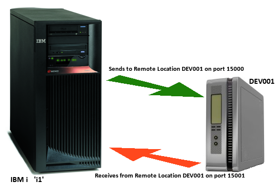
The previous diagram shows a simple configuration where the IBM i (i1) communicates directly with the Enterprise Console (DEV001).
The respective configurations on both the IBM i and Device Manager (for Enterprise Console) would be:
For IBM i (i1) - Work with Remote Locations
Originating Device
-
Name: *SYSTEM
-
IP Address: 192.168.0.35
-
Port: 15001
Remote Location
-
Name: DEV001
-
IP Address: 192.168.0.138
-
Port: 15000
For Enterprise Console - Device Manager
-
Name: i1
-
Type: IBM i
-
IP Address: 192.168.0.35
-
Port: 15001
With this configuration in place, IBM i device ‘i1’ sends data to the Enterprise Console (DEV001) via port 15000 and receives data from DEV001 on port 15001. DEV001 sends data on port 15001 and receives from HAL501P1 on port 15000.
Forwarding via an intermediate system
There may be instances where a direct connection cannot be made between the IBM i device and the Enterprise Console. In such instances it is possible to route the data via another IBM i device that does have a direct connection. This is done using the ‘Forwarding port’ parameter within the remote location.
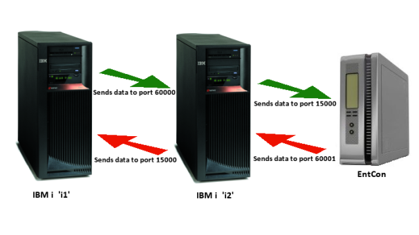
In this next example, IBM i device ‘i1’ cannot communicate directly with Enterprise Console. However it can talk to another IBM i device ‘i2’ which in turn can communicate directly with the Enterprise Console.
The following configuration would be required for this scenario.
|
Systems |
i1 |
i2 |
EntCon |
|
Originating Device |
*SYSTEM |
*SYSTEM |
EntCon |
|
IP Address |
192.168.0.18 |
192.168.0.35 |
192.168.0.138 |
|
Port |
15001 |
15005 |
15000 |
|
|
|
|
|
|
Remote Location 1 |
|
|
Dev Manager |
|
Name |
i2 |
i1 |
i2 |
|
IP Address |
192.168.0.35 |
192.168.0.18 |
192.168.0.35 |
|
Remote Port |
15005 |
15001 |
15005 |
|
Forwarding Port |
*NONE |
60001 |
N/A |
|
|
|
|
|
|
Remote Location 2 |
|
|
Dev Manager |
|
Name |
EntCon |
EntCon |
i1 |
|
IP Address |
192.168.0.35 |
192.168.0.138 |
192.168.0.35 |
|
Remote Port |
60000 |
15000 |
60001 |
|
Forwarding Port |
*NONE |
60000 |
N/A |
Using this configuration, data from ‘i1’ that is to be sent to the Enterprise Console must travel through ‘i2’.
Therefore, data is sent from ‘i1’ to EntCon gets sent to ‘i2’ on port 60000. ‘i2’ collects the data on port 60000 and forwards it to EntCon on port 15000. EntCon then sends back data via ‘i2’ on port 60001 and which then forwards it to ‘i1’ on port 15000.
Remote Locations and IP Address Mapping
Remote locations support IP Address mapping for forwarding ports so that it is possible to forward alerts from one IBM i to another and then onto the Enterprise Console, so that the IP address of the originating machine is identifiable.
IP Address mapping is set up using option 42=Configuration followed by option 5=Work with IP Address Mappings. See ‘Work with IP Address Mappings’ for more information.
Device Naming Conventions
When data is forwarded to the Enterprise Console from an intermediate device, it the name of this device that is displayed in the Enterprise Console, which may confuse as to the origin of the alert. In order that the originating device is correctly identified, and providing that it has been correctly configured within Device Manager, the ‘Device name’ parameter for the originating device, changes to ‘Display Name’ when an alert has been forwarded through an intermediate system.
Receive wait time-out
Specifies the maximum time to wait when receiving data from a remote system after accepting a connection.
Batch mode time-out
Specifies the time period (in minutes), within which attempts are made to send data to the remote location. If the remote system cannot be contacted, retries are attempted from time to time until the time specified here expires. The data is then set to time-out status and no further send attempts are made.
Interactive time-out
Specifies the time period (in seconds), in which a response should be received for an interactive request, such as F4=Prompt being pressed to obtain a list of valid entries. If the response is not received within this time, the request is canceled.
Handshake interval
Specifies the handshake interval for this remote system. This is the frequency with which the local system verifies that the remote system can still be contacted. The lower the number the greater the frequency with which the contact is made, thus giving a faster indication should connection be lost.
This parameter defaults to 1 minute if not manually set.
Data encoding
Specifies the data encoding to use when sending data to this remote location:
| *ASCII | Data is encoded as 8 bit ASCII Latin No.1 to ISO 8859 using CCSID 819 |
| *UTF8 | Data is encoded as UTF-8 using CCSID 1208 |
Short code
Specifies the short code used to identify this remote system. The short code prefixes the alert ID to form the alert reference used when alerts are sent from this system as email or SMS messages.
It may also be used with the Close Alert (CLSALT) and Reply by Alert ID (RPYALT) commands to close or reply to a specific alert on a remote system.
Short codes are 1 to 3 characters in length in the range A to Z. Numbers and other characters are not allowed. Short codes are not case-sensitive.
The following functions are available when adding a remote location:
F3=Exit
Use F3=Exit to close the current display and return to the main menu.
F5=Refresh
Use F5=Refresh to update the display with current information.
F12=Cancel
Use F12=Cancel to exit this display and return to the previous display.