Fuzz Testing a CAN bus OBDII Connection with AnaGate CAN X2/FX2 Hardware
Overview
This guide covers testing for the following automotive modules in beSTORM:
-
CANBUS
-
J1939-21
-
OBDII
-
Unified Diagnostic Services
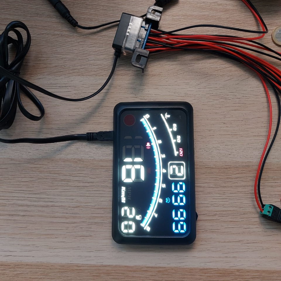
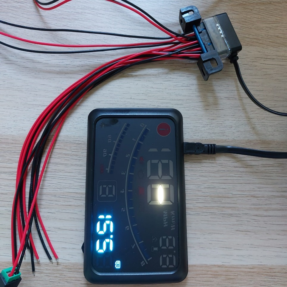
The CANBUS module tests the CAN bus system low-level protocol. All other protocols are higher-layer protocols built on top of CAN. This guide will show an example on how to connect beSTORM to a Car HUD (head-up display) which is the device under testing (DUT) for this guide using the AnaGate X2/FX2 (CANbuster) hardware.
Testing environment
To perform this test, you will need the following:
-
beSTORM 12.4.9 or later (licensed)
-
(1) AnaGate CAN X2/FX2 (CANbuster) hardware (https://www.anagate.de/en/)
-
(1) Ethernet cable
-
(1) J1962 OBD2 female connector to open cable (for example, https://www.amazon.com/J1962F-Female-Assembled-Connector-Harness/dp/B0BVMHVGKW?th=1)
-
(1) Female DC power pigtail cable (for example, https://www.amazon.com/Pigtail-Security-Connectors-Surveillance-MILAPEAK/dp/B071VTBQNG)
-
(1) Female DC power jack adapter connector (for example, https://www.amazon.com/Ksmile%C2%AE-Female-2-1x5-5mm-Adapter-Connector/dp/B015OCV5Y8)
-
(2) Power supply adapter to DC 12V (for example, https://www.amazon.com/Charger-Compatible-Electric-Machine-Scooter/dp/B0BB6W84KW)
-
(1) OBD2 head-up display (for example, https://www.amazon.com/ACECAR-Universal-Interface-Measurement-Temperature/dp/B07NQ9LTGX)
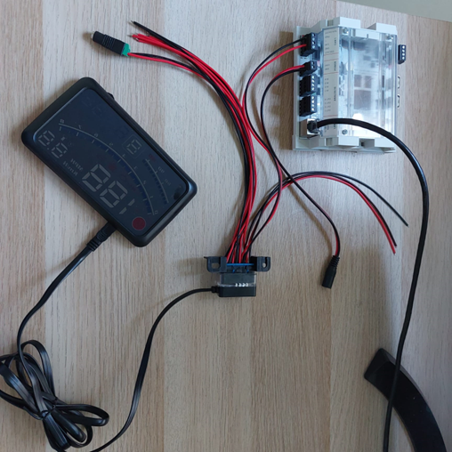
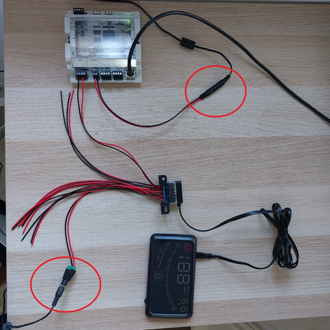
Connect the hardware
-
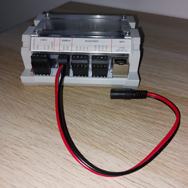
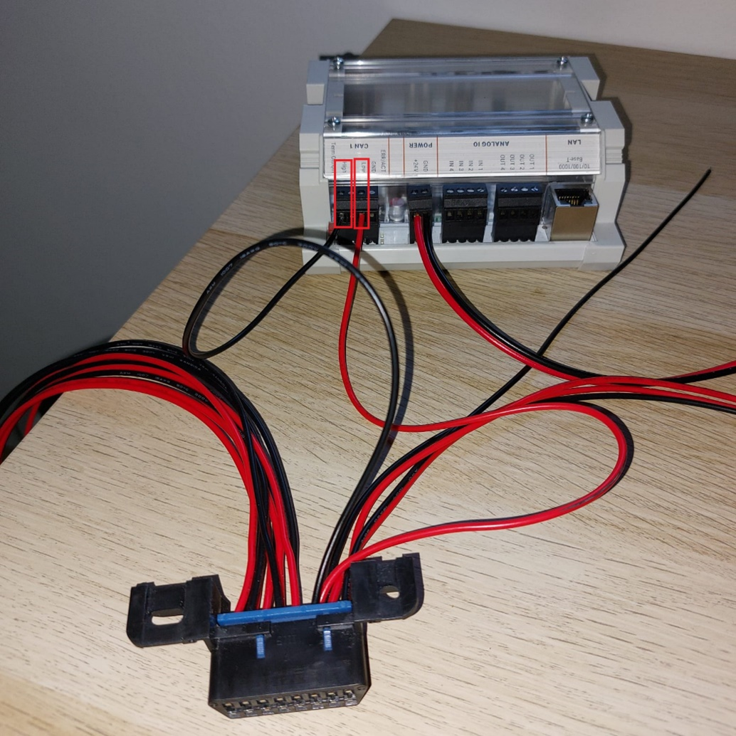
Connect the female DC power pigtail cable to the CANbuster hardware's POWER connector. You will connect the other end of the pigtail cable to one of the power supply adapters in a later step.
-
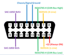
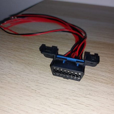
Referring to the J1962 OBD2 female connector to open cable schema below, do the following:
-
Connect pin 6 of the J1962 OBD2 female connector to open cable to the CANbuster hardware's High connector.
-
Connect pin 14 of the J1962 OBD2 female connector to open cable to the CANbuster hardware's Low connector.
-
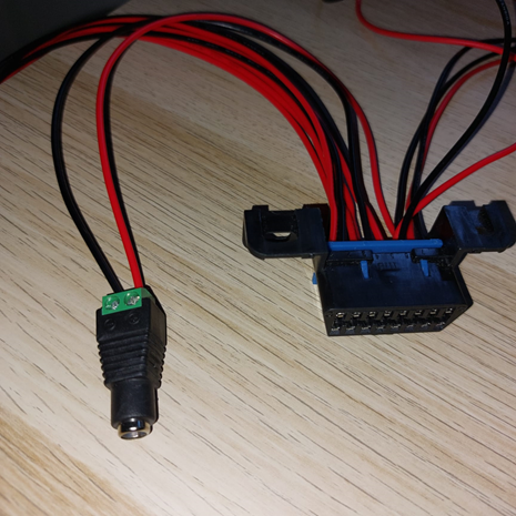
Connect pins 4 and 16 to the female DC power jack adapter connector, which you will later connect to one of the power supply adapters.
-
-
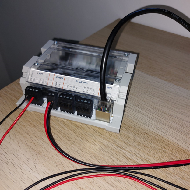
Connect one end of the Ethernet cable to the CANbuster's LAN connector, and then connect the other end to the beSTORM computer's Ethernet jack.
-
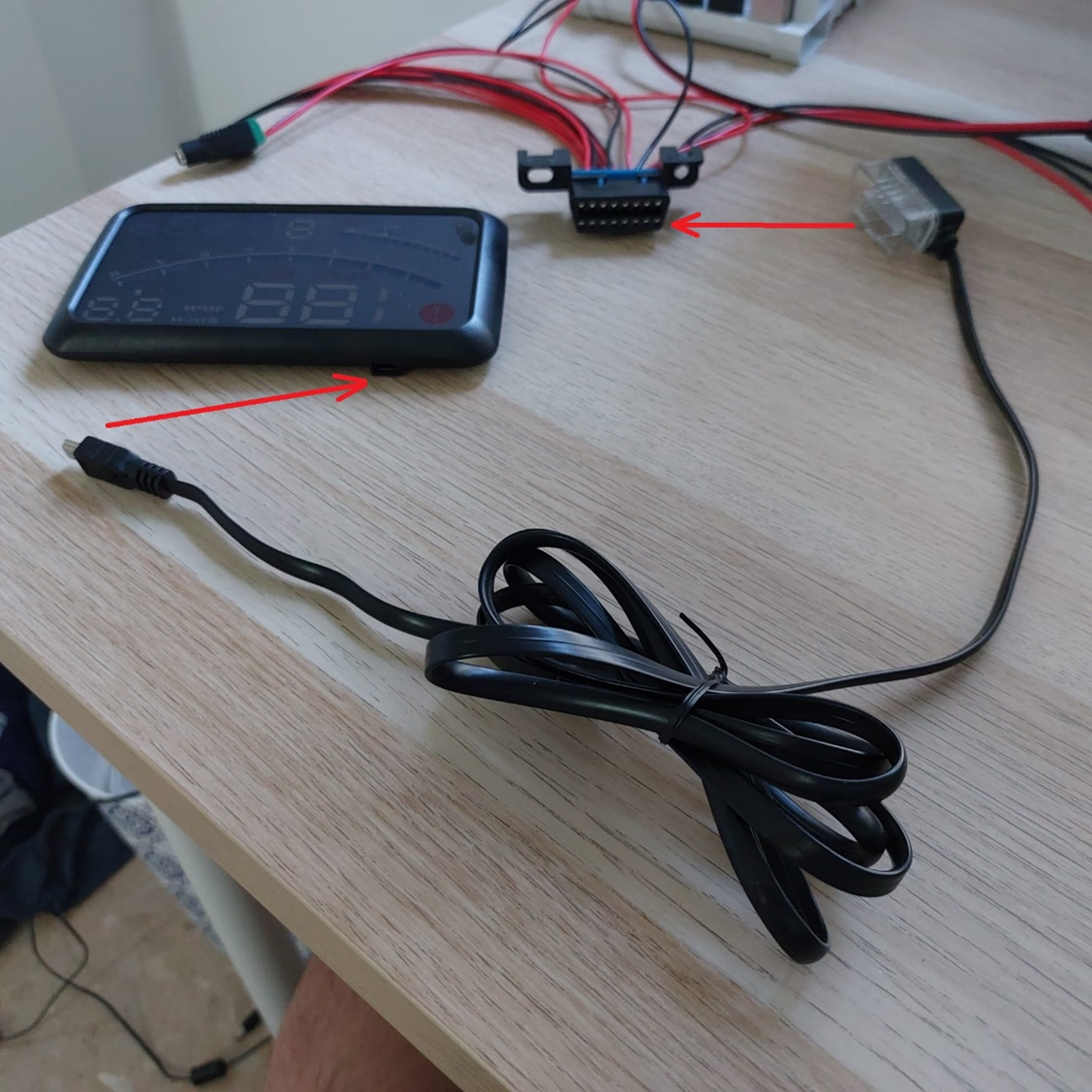
Connect the USB end of the OBD2 cable (included with the HUD) to the HUD. Then, connect the OBD2 end of the cable to the J1962 OBD2 female connector to open cable.
-
Using the two power supply adapters to DC 12V, do the following:
-
Connect one adapter to the female DC power pigtail cable from step 1.
-
Connect the other adapter to the female DC power jack adapter connector from step 2c.
-
-
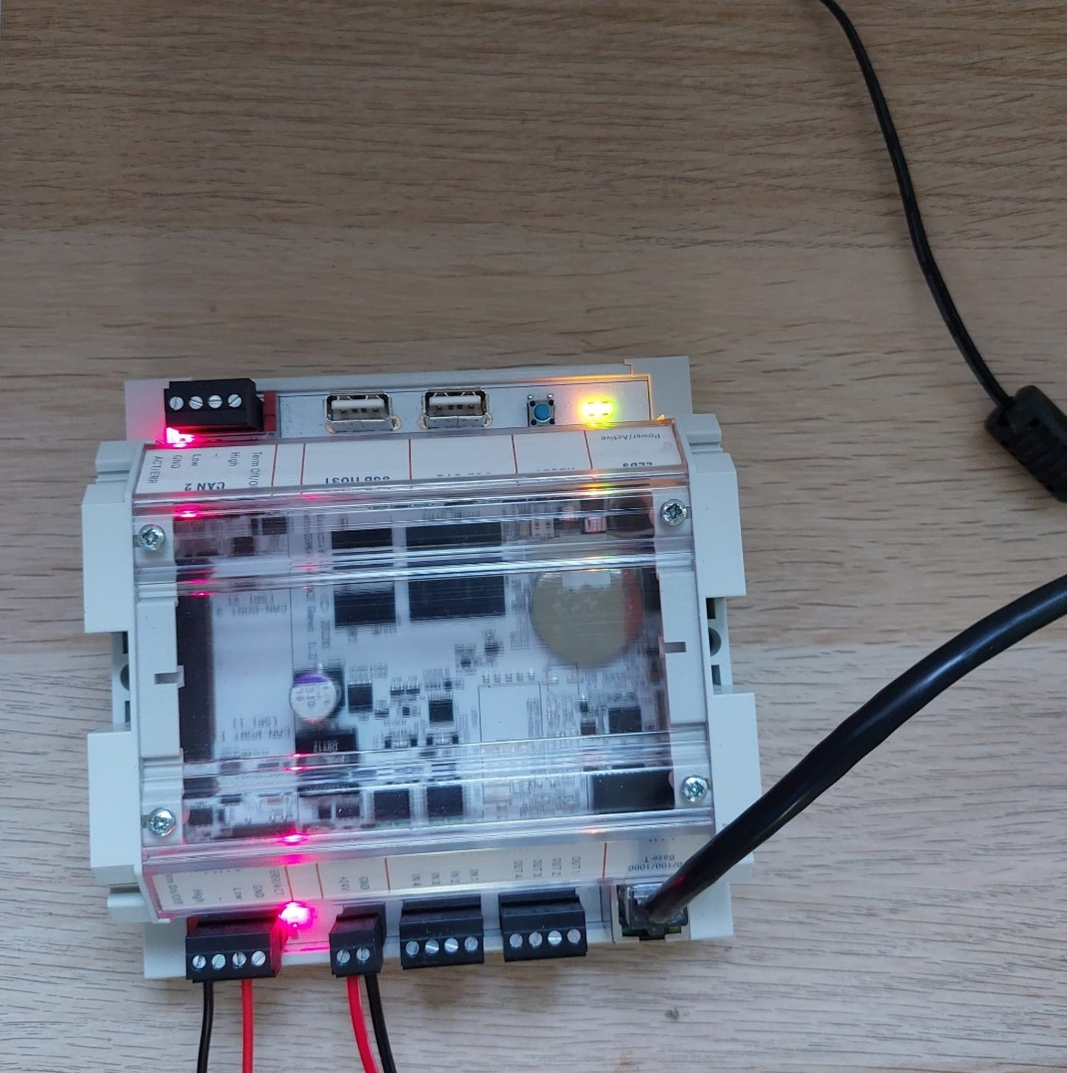
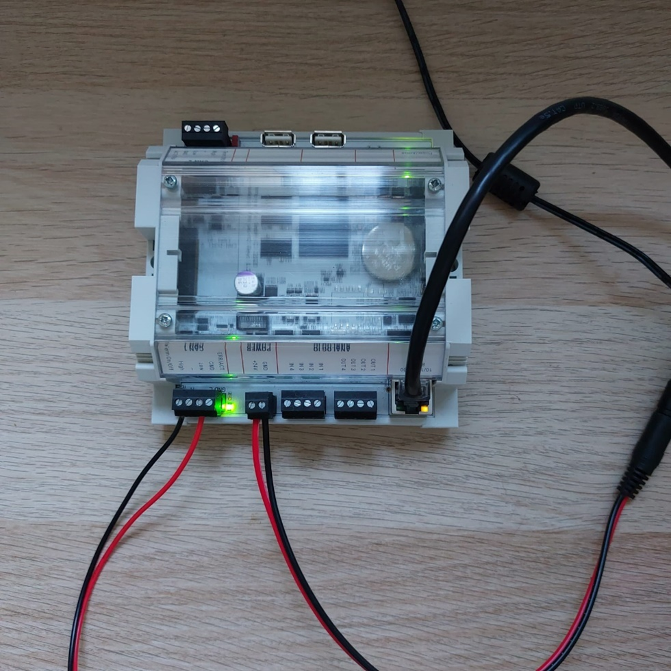
Connect the power supply for the CANbuster hardware. Once it powers on, you will see these LEDs:
After a few seconds, the Power LED will turn green:
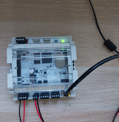
Once the power supply is connected to the HUD, you should see the green LED for the CAN connector on the CANbuster hardware turn on:
Set up a TCP/IP connection
Before you can start fuzz testing from beSTORM to the DUT (that is, the HUD), you will need to configure a TCP/IP connection that uses the Ethernet cable currently connected to the beSTORM computer and the CANbuster hardware.
By default, the CANBuster hardware is configured with the following initial network settings:
-
IP address - 192.168.1.254
-
Address type - static Network mask 255.255.255.0
The beSTORM computer's Ethernet port needs to be in the same subnet as the CANBuster. To do this:
-
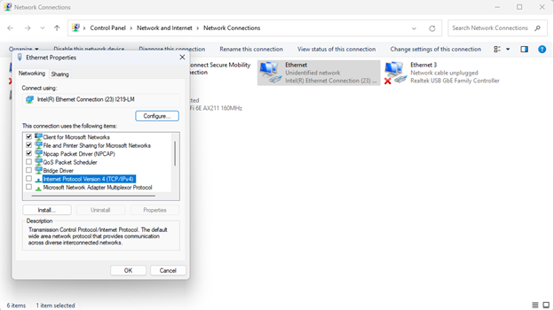
In Windows, go to View Network Connections, right-click the Ethernet port currently connected to the CANbuster hardware, and then select Properties.
-
From the list of options under the Networking tab, select the Internet Protocol Version 4 (TCP/IPv4) checkbox, and then select Properties.
-
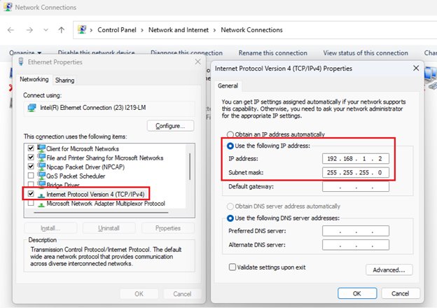
Select Use the following IP address and enter the following values:
-
IP address - 192.168.1.2
-
Subnet mask - 255.255.255.0
-
-
Ping the CANbuster IP address (192.168.1.254) to ensure the connection is working.
TIP: You can access CANBuster settings through a standard browser (Edge, Firefox, Chrome, etc.) at http://192.168.1.254 .
Fuzzing with beSTORM
-
Open beSTORM Client.
-
Select New Project. The beSTORM New Project Wizard opens.
-
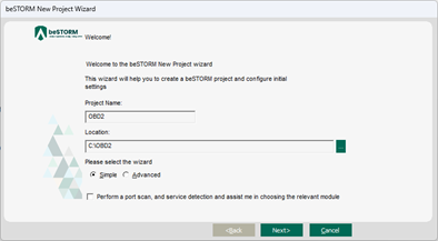
On wizard's Welcome page, do the following:
-
In the Project Name box, enter a name.
-
Optionally, select a different file location for your project in the Location Name box.
-
Leave Please select the wizard set to Simple.
-
Leave Perform a port scan, and service detection and assist me in choosing the relevant module unchecked.
-
-
Select Next.
-
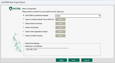
On the Basic Configuration page, do the following:
-
Select OBDII from the Automotive group of beSTORM's predefined modules list.
-
In the Hostname or IP address box, enter 192.168.1.254 (IP address of the CANbuster hardware).
-
-
Select Next.
-
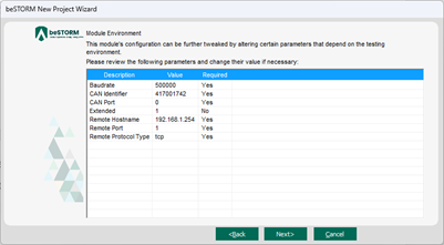
On the Module Environment page, leave all parameters to their default setting.
-
Select Next.
-
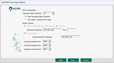
On the Extra Configuration page, set the Saturation Rate Threshold parameter to less than 100 (for example, 15). Leave all other parameters to their default setting.
-
Select Next.
-
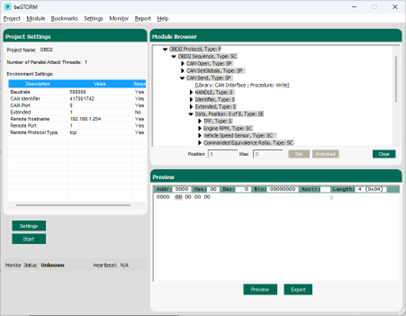
On the Complete beSTORM wizard page, clear the Auto-start beSTORM scan now checkbox and then select Finish. The beSTORM Client window opens.
-
Select Start to begin fuzz testing.
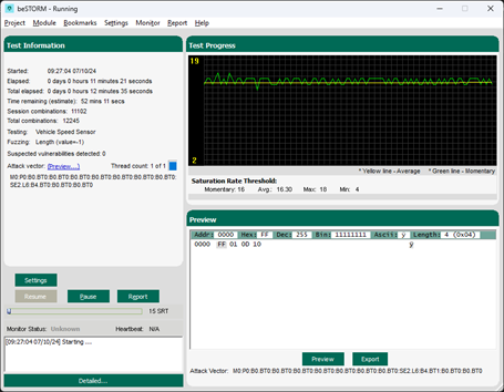
The HUD should start displaying data from beSTORM.