Fuzz Testing USB Devices
Overview
This topic focuses on acquiring, installing, and fuzzing with the EZ-USB FX3 board. For more information on the UAC USB Peripheral Module, see the beSTORM UAC USB Peripheral Module Guide on Fortra's Beyond Security Portal.
Acquire the hardware
Before you can fuzz with beSTORM, you must supply the following third-party hardware:
-
(1) CYUSB3KIT-003 EZ-USB FX3 SuperSpeed Explorer Kit (to purchase, go to https://www.infineon.com/cms/en/product/evaluation-boards/cyusb3kit-003/)
-
This kit includes:
-
(1) EZ-USB FX3 board
-
(1) USB 3.0 A to B cable
-
(4) plastic board jumpers (two jumpers will come preinstalled on the board)
-
(1) EZ-USB FX3 SuperSpeed Explorer Kit Quick Start Guide (you will use this to identify parts of the board in later sections)
-
-
-
(1) USB 2.0 A to 5-pin Micro-USB Type B cable
Install the EZ-USB FX3 board
After you obtain the EZ-USB FX3 SuperSpeed Explorer Kit, do the following:
Download and install the Windows driver
-
Under the Windows section, select USB-Serial Windows Driver Installer to download the CypressDriverInstaller_1.exe file. You may need to create a Infineon account to download this file.
-
Double-click the CypressDriverInstaller_1.exe file, and then proceed through the installer to install the driver.
Connect the EZ-USB FX3 board to the beSTORM computer
-
Place one of the plastic jumpers included with the kit over the PMODE Jumper (J4) pins on the board (this sets the jumper to the closed state and configures the board for firmware flashing in the Flash the EZ-USB FX3 board's firmware section).
-
Connect the USB 3.0 cable included with the kit to the USB 3.0 port on the board, and then connect the other end of the USB cable to the beSTORM computer.
NOTE: For the locations of the PMODE Jumper (J4) and USB 3.0 port on the board, refer to the EZ-USB FX3 SuperSpeed Explorer Kit Quick Start Guide included with the kit.
Verify the EZ-USB FX3 board is properly detected by the beSTORM computer
-
In Windows, open Device Manager.
- Expand Universal Serial Bus controllers.
-
Verify Cypress FX3 USB Bootloader Device appears in the list. If the device does not appear in the list, try reinstalling the Windows driver or contact Infineon technical support.
Flash the EZ-USB FX3 board's firmware
After installing the EZ-USB FX3 board on the beSTORM computer, do the following:
Download and unzip the firmware file
-
Download UAC_USB_Peripheral_Module.zip.
-
Unzip the file to extract the UAC_USB_Peripheral_Module folder. This folder also includes files you will use for fuzzing a USB device in the How to fuzz a USB device with the EZ-USB FX3 board section.
Download the flashing tool
-
Go to https://www.infineon.com/cms/en/product/evaluation-boards/cyusb3kit-003/#!designsupport.
-
Select Read More for DOWNLOAD - SuperSpeedExplorerKitSetup_RevSS.exe to download the tool.
-
Double-click the SuperSpeedExplorerKitSetup_RevSS.exe file, and then start proceeding through the installer.
-
When prompted, select Typical as the Installation Type and then complete the rest of the installer.
Flash the EZ-USB FX3 board
-
On the beSTORM computer, open C:\Program Files (x86)\Cypress\EZ-USB FX3 SDK\1.3\bin.
-
Double-click CyControl.exe. The USB Control Center opens.
-
Select Program > FX3 > I2C EEPROM.
-
Select the UAC_USB_Peripheral_Module folder you extracted in step 2 of Download and unzip the firmware file, and then select the best_uac_usbd.img firmware file.
-
Select Open to start flashing the firmware. The USB Control Center will display Programming of I2C EEPROM in Progress while the USB Control Center is flashing the EZ-USB FX3 board. Once the flashing process is complete, the message will change to Programming of I2C EEPROM Succeeded, indicating the flashing process is complete.
-
Disconnect the USB 3.0 cable from the EZ-USB FX3 board.
-
Remove the plastic jumper from the PMODE Jumper (J4) on the EZ-USB FX3 board to set it back to the open state. Your EZ-USB FX3 board is now ready to fuzz a USB device with beSTORM.
How to fuzz a USB device with the EZ-USB FX3 board
After installing the EZ-USB FX3 board on the beSTORM computer and then flashing its firmware, do the following:
Connect the EZ-USB FX3 board to the computer and the target USB device
-
Insert the USB 3.0 cable included with the EZ-USB FX3 SuperSpeed Explorer Kit into the USB 3.0 port on the board, and then connect the other end of the cable to the target USB device you want to fuzz.
-
Insert the USB 2.0 Micro USB cable you supplied separately from the kit into the USB 2.0 port on the board, and then connect the other end of the cable to the beSTORM computer.
NOTE: For the locations of the USB 3.0 port and USB 2.0 port on the board, refer to the EZ-USB FX3 SuperSpeed Explorer Kit Quick Start Guide included with the kit.
Verify the EZ-USB FX3 board and target USB device are properly detected by the beSTORM computer
-
In Windows, open Device Manager.
-
Expand Universal Serial Bus controllers.
-
Verify the USB-Serial (Dual Channel) Vendor 1 and USB-Serial (Dual Channel) Vendor MFG devices appear in the list.
NOTE: If you do not see USB-Serial (Dual Channel) Vendor 1 and/or USB-Serial (Dual Channel) Vendor MFG in your list of USB devices, contact Fortra's Beyond Security Technical Support at support@beyondsecurity.com.
Prepare the project fuzzing files
-
On the beSTORM computer, create the following folder: C:\TEMP.
-
Copy the best_uac_usbd.dll, bestorm.csv and best_uac_usbd.xml files from the UAC_USB_Peripheral_Module folder (steps 1a-1c of the Flash the EZ-USB FX3 board's firmware section) into the C:\TEMP folder.
Create a new beSTORM project and start fuzzing
-
Open beSTORM Client.
-
Select New Project. The beSTORM New Project Wizard opens.
-
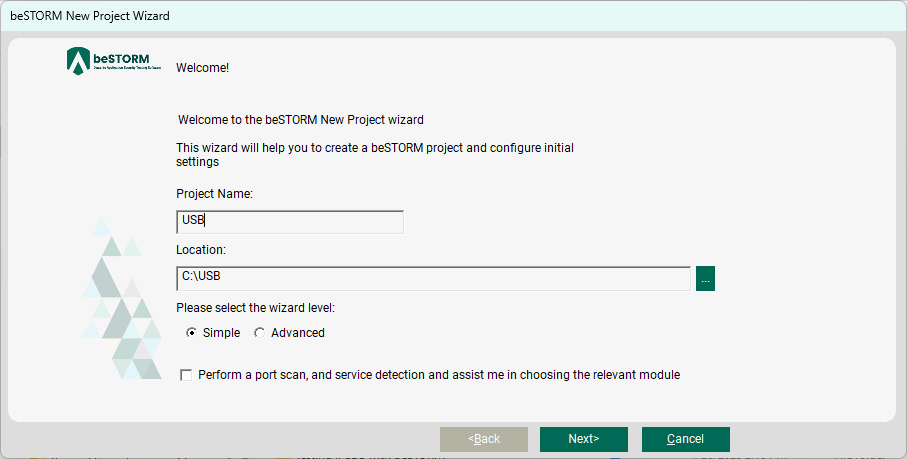
On the Welcome page, do the following:
-
In the Project Name box, enter a name.
-
Optionally, select a different file location for your project in the Location Name box.
-
Leave Please select the wizard set to Simple.
-
Leave Perform a port scan, and service detection and assist me in choosing the relevant module unchecked.
-
-
Select Next.
-
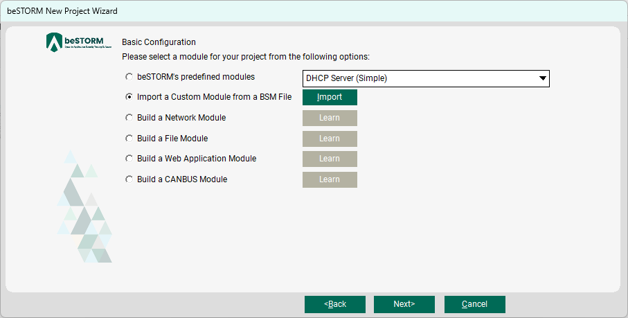
On the Basic Configuration page, select Import a Custom Module from a BSM file, and then select Import.
-
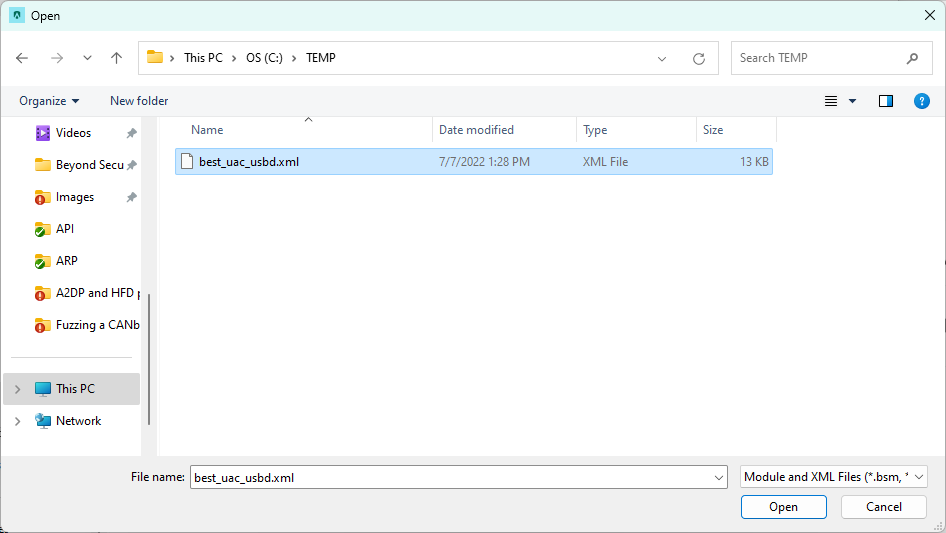
In the dialog box that appears, select the C:\TEMP folder, and then select the best_uac_usbd.xml file.
-
Select Open.
-
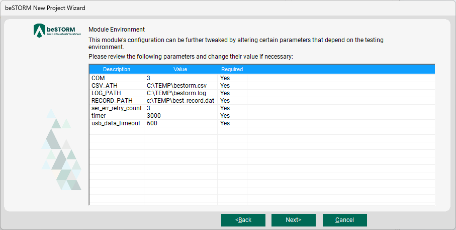
On the Module Environment page, proceed with the default values shown.
-
Select Next.
-
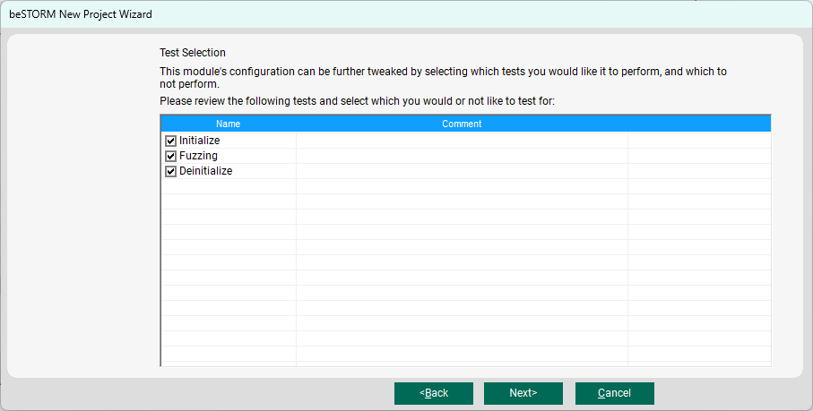
On the Test Selection page, leave the Initialize, Fuzzing, and Deinitialize checkboxes selected.
-
Select Next.
-
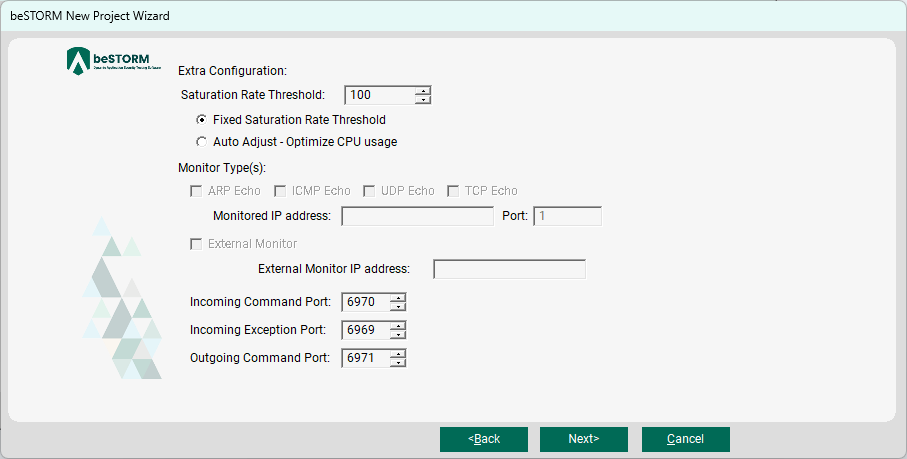
On the Extra Configuration page, proceed with the default values for all settings.
-
Select Next.
-
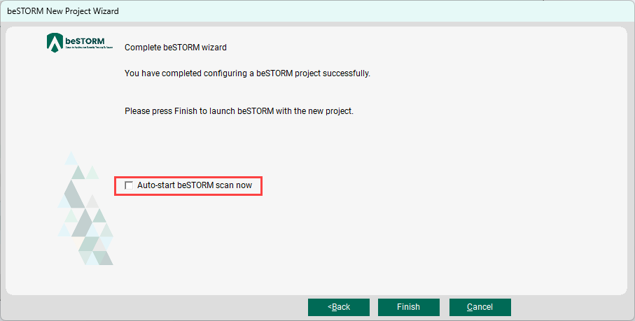
On the Complete beSTORM wizard page, clear the Auto-start beSTORM scan now checkbox to disable this option.
-
Select Finish.
-
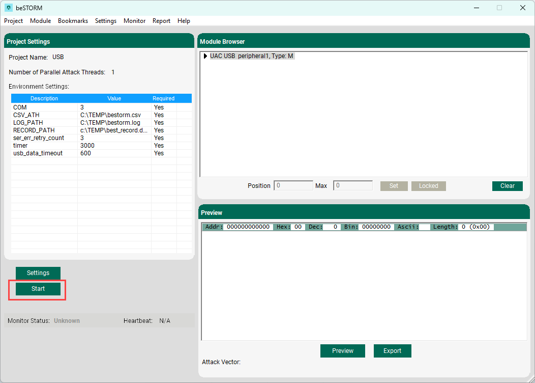
In the Project Settings pane on the main beSTORM client screen, select Settings.

-
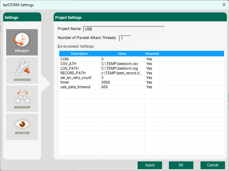
In the Project Settings pane of the beSTORM Settings dialog box, review the following settings for your environment:
-
LOG_PATH - The default path and file name for the project's log file is C:\TEMP\bestorm.log. Optionally, you can change either by using alphanumeric characters and entering a different file name (must end with .log) and path to store the log file.
-
RECORD_PATH - The default path and file name for the project's recovery data file are c:\TEMP\best_record.dat. Optionally, you can change either by using alphanumeric characters and entering a different file name (must end with .dat) and path to store the recovery data file for the recovery tool in your environment. For more information about recovery tools, refer to the Recovery Tool chapter in the beSTORM UAC USB Peripheral Module Guide.
-
Proceed with the default values for the remaining settings.
-
-
Select Apply.
-
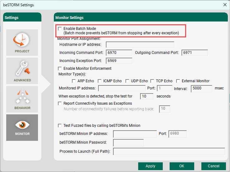
From the left pane on the beSTORM Settings dialog box, select Monitor.
-
Under Monitor Settings, clear the Enable Batch Mode checkbox to disable this option.
-
Select Apply.
-
Select OK.
-
In the Project Settings pane on the main beSTORM Client window, select Start.
 NOTE: The "Can't open SerialPort" error message will appear if a serial port or a file cannot be opened. If this occurs, check the settings for your environment again.
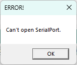
-
A dialog appears, requesting you to Please reset the device. Do not select OK until after the next step.
-
Press the Reset Switch on the EZ-USB FX3 board.
NOTE: For the location of the Reset Switch on the board, refer to the EZ-USB FX3 SuperSpeed Explorer Kit Quick Start Guide included with the kit. -
Select OK in the Please reset the device dialog to start fuzzing the target USB device.
When the ScaleType is standard (Base2+/-1), it sends ~1200 fuzz data. Fuzzing may take 3 to 4 hours, depending on the environment.
When you run a test, a log file and a record file for the recovery tool are created separately from the standard log file.